
A Descon project keeps every connection on a job in one file. Instead of opening designs one at a time, you see them all in one list with their members, their capacity and any checks that fail. You can bring a whole building's worth of connections into it at once, change the code or the bolts on all of them together, and send a report for each one to a folder in a single step.
This page walks through a real project from start to finish. It uses nineteen connections from a steel office building: shear tabs, clip angles and end plates on the gravity framing, three moment connections, four braced-frame connections and a beam splice. The screenshots are from Descon 8.1.
Projects are part of the Next plan, which is also what the free trial runs. Basic and Standard do not show the Project tab.
On this page
- The project view
- Bring in the connections you already have
- Reading the project
- Working on one connection
- Quick edits without leaving the list
- Repeating a typical connection
- Changing every connection at once
- Filters and batch edits
- Finding what does not work
- Reports for the whole project
- Saving and sharing a project
- The project toolbar
- Common questions
The project view
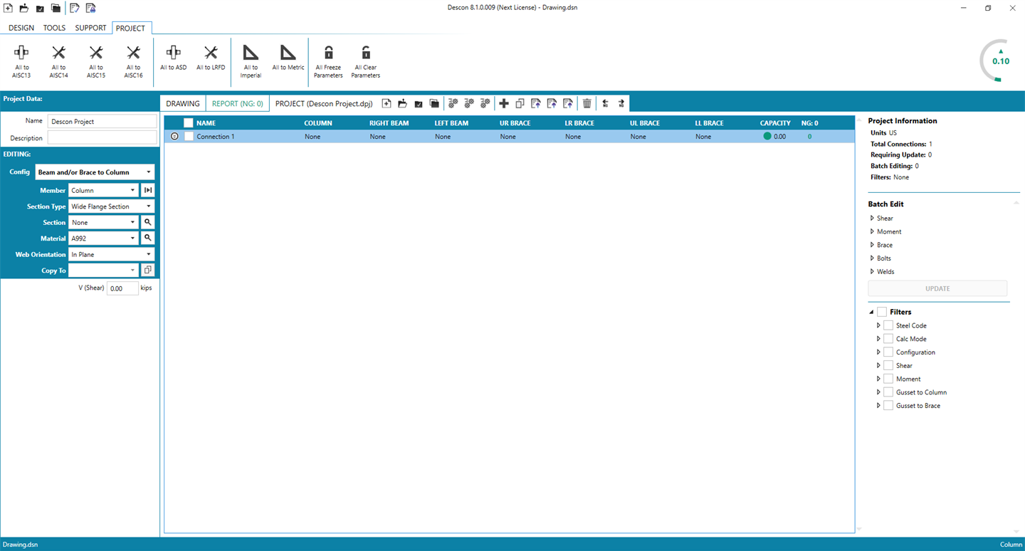
Descon has three views of the work in front of you: DRAWING, REPORT and PROJECT. They sit in the bar above the drawing. Press PROJECT, or open the PROJECT tab on the ribbon, and the drawing is replaced by the list of connections in the current project.
Descon always has a project open, even when you are working on a single design. A new one holds a single blank connection, named Connection 1. Give the project a name and a description in Project Data on the left. The button in the view bar shows the file name, which is Descon Project.dpj until you save it under another.
Bring in the connections you already have
Most jobs start with designs that already exist: a typical shear tab from the last project, the moment connections you checked last week, a folder of .dsn files from a colleague. Press Import Connections From .dsn Files in the project toolbar and pick as many of them as you like. Click one file and press Ctrl+A to take the whole folder.
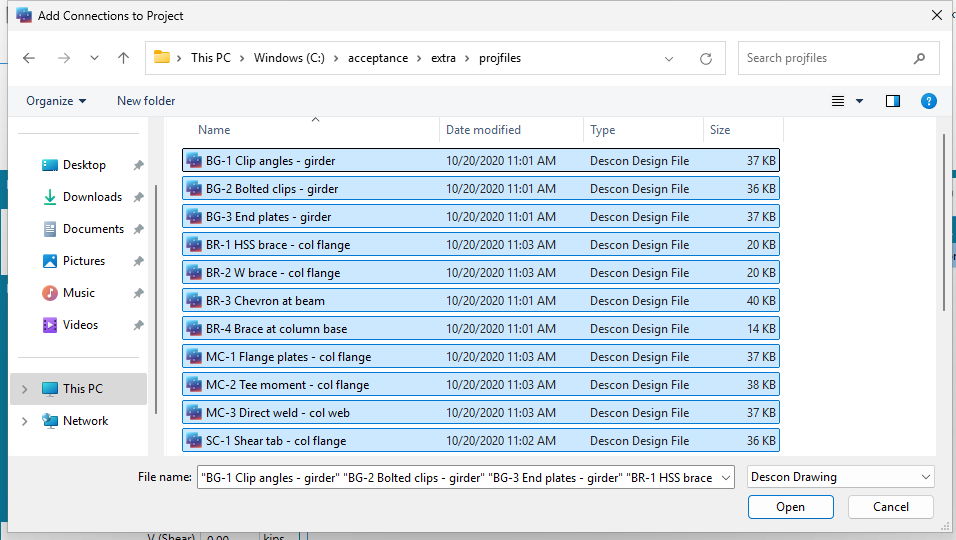
Each file becomes one connection, named after the file, and Descon calculates them all as they come in. Nineteen designs took about fifteen seconds. The files themselves are copied into the project, not linked: later changes to a .dsn file do not reach the project, and changes in the project do not reach the file.
If you started with the blank Connection 1, tick its box and press Remove Selected Connections. A project always keeps at least one connection, so you cannot remove the last one.
Reading the project
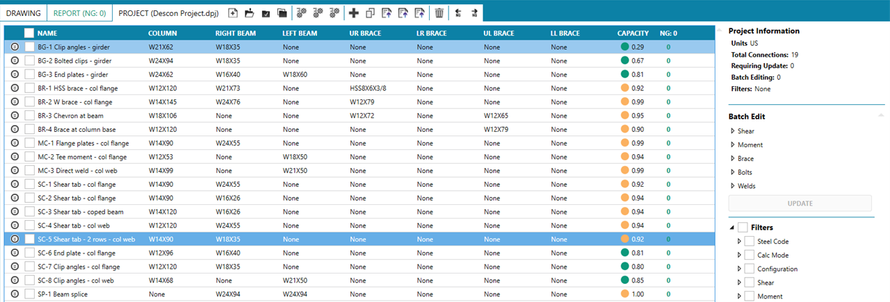
Each row is one connection. The columns show:
- NAME: the name you gave it, or the file it came from.
- COLUMN, RIGHT BEAM, LEFT BEAM and the four brace columns: the members at each position. None means that position is empty. For a beam-to-girder connection, the girder is listed as the column.
- CAPACITY: the highest ratio of demand to strength in the connection, with a dot to read it at a glance. Green is comfortably within capacity, orange is close to it, and red is over. Descon sizes each connection to its loads, so values close to 1.00 are normal; anything above 1.00 fails. It reads UPDATE when something has changed and the connection has not been calculated since.
- NG: how many checks in that connection fail. The column heading shows the total for the project.
On the right, Project Information gives the unit system, how many connections there are, how many are waiting to be calculated, how many are ticked for a batch edit, and which filters are on.
Working on one connection
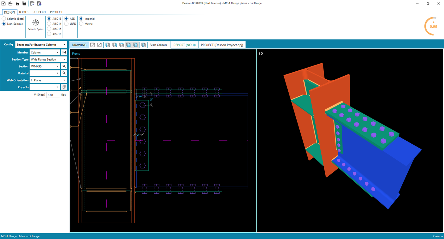
Click a row and that connection is loaded into the design panel on the left, exactly as if you had opened its file. EDITING: above the panel names it. Switch to DRAWING or REPORT to see it and change anything you would change in a single design. The changes are kept in the project. Back in the project view the row reads UPDATE until you press Calculate.
Quick edits without leaving the list
Many changes do not need the full design panel. Click the round expander at the start of a row and the row opens up to show every member in the connection: its name and configuration, the column, each beam's shape, shear connection type, reaction and moment, and each brace's shape, connection types and forces.
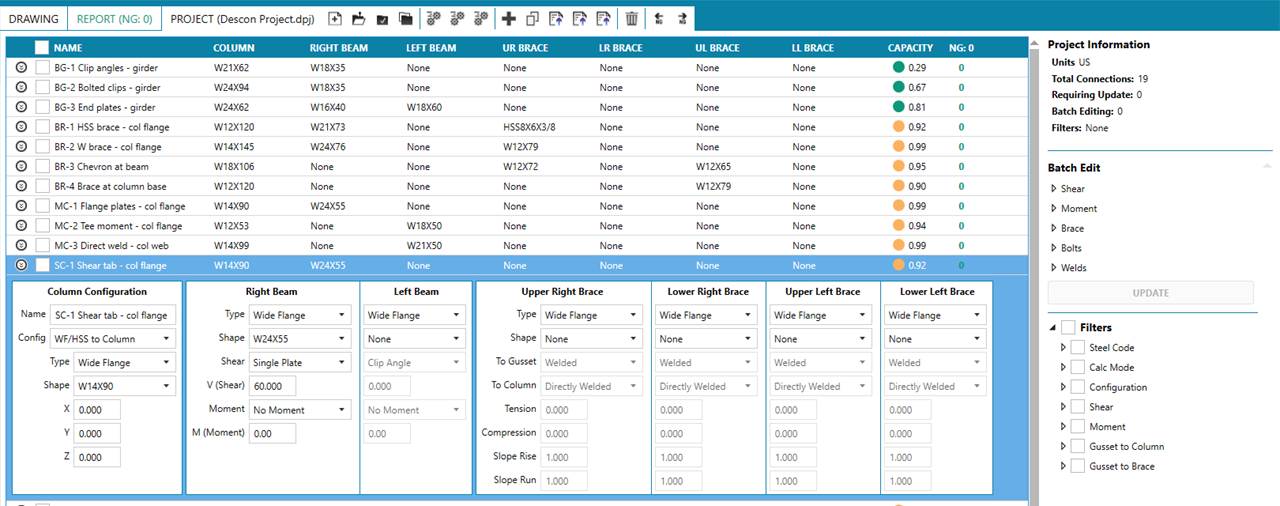
Anything you change here marks the connection for recalculation. Click the expander again to close it.
Repeating a typical connection
A building has far more connections than it has connection types. Once one is right, tick it and press Copy Selected Connections. The copy lands at the bottom of the list as Connection followed by a number, with every setting of the original. Open its row, give it its own name and reaction, and it is a new connection.
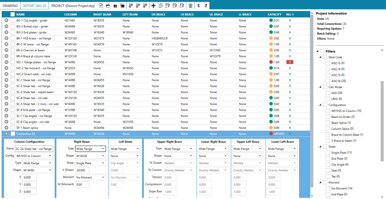
A copy is not calculated until something in it changes. Its capacity reads 0.00 at first, and UPDATE once you have edited it. Press Calculate and the real number appears: SC-2A, with 28 kips, came out at 0.82.
Changing every connection at once
The PROJECT tab on the ribbon applies a change to every connection in the project:
- All to AISC13 through All to AISC16: the steel specification.
- All to ASD and All to LRFD: the design method.
- All to Imperial and All to Metric: the unit system. The values are converted, not reinterpreted.
- All Freeze Parameters and All Clear Parameters: freeze every value Descon chose, so a later calculation checks the connection as it stands rather than designing it again, or release them so it designs them afresh.
The designs in this example were made to the 13th Edition (AISC13). One press of All to AISC16 moved all nineteen to the 16th Edition. The capacity column switched to UPDATE on every row, and Requiring Update read 19.
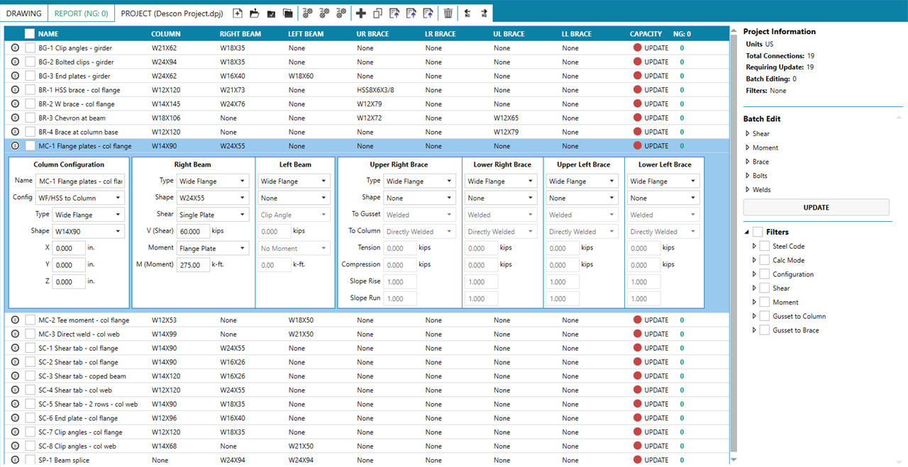
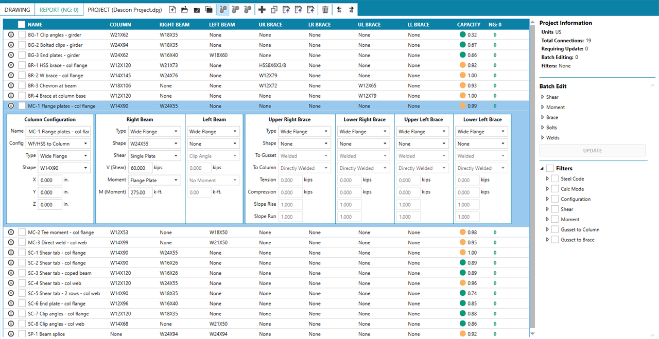
Press Calculate in the project toolbar and every connection that needs it is designed again. Here that took about seven seconds for all nineteen.
Changing ASD to LRFD changes how the loads are read; it does not factor them for you. A reaction entered as a service load under ASD becomes a factored load under LRFD. Check the loads before you switch a project's method.
Filters and batch edits
The Filters panel on the right sorts the project by steel code, design method, configuration, shear connection, moment connection and the gusset connections, with a count beside each value. Tick a value to show only those connections. Ticks in the same group add together, so Single Plate and Clip Angle shows both; ticks in different groups narrow the list.
With the list filtered, the box at the top of the tick column selects every connection that is showing and no others. Batch Editing counts them. Then open a group in Batch Edit, set the value, tick the box beside it, and press UPDATE:
- Shear: the reaction, the shear connection type, or both.
- Moment: the moment, the moment connection type, or both.
- Brace: the brace-to-gusset and gusset-to-column connections.
- Bolts: the bolt diameter, for every bolt group in the connection.
- Welds: the electrode.
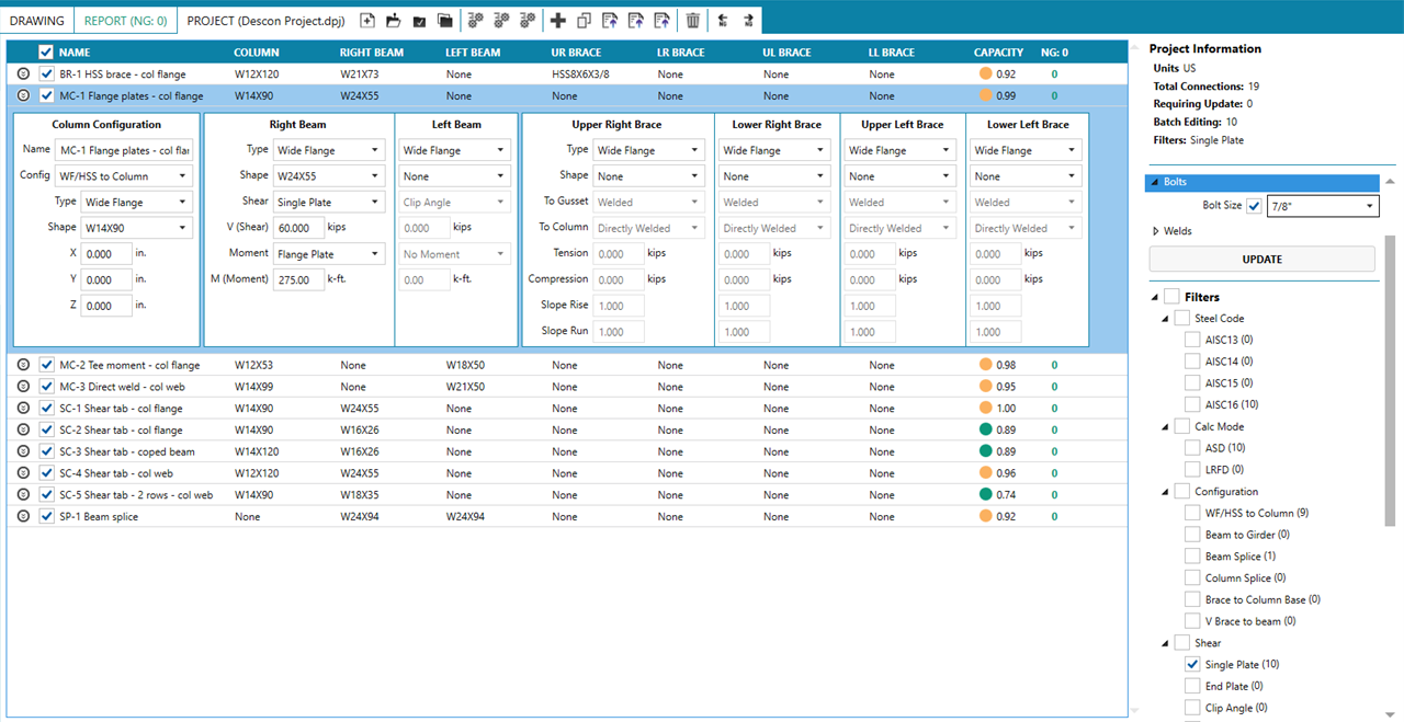
In this example the office standard moved to 7/8 in. bolts. Filtering on Single Plate left ten connections showing. Selecting them all, setting Bolt Size to 7/8" and pressing UPDATE changed and recalculated all of them in one step.
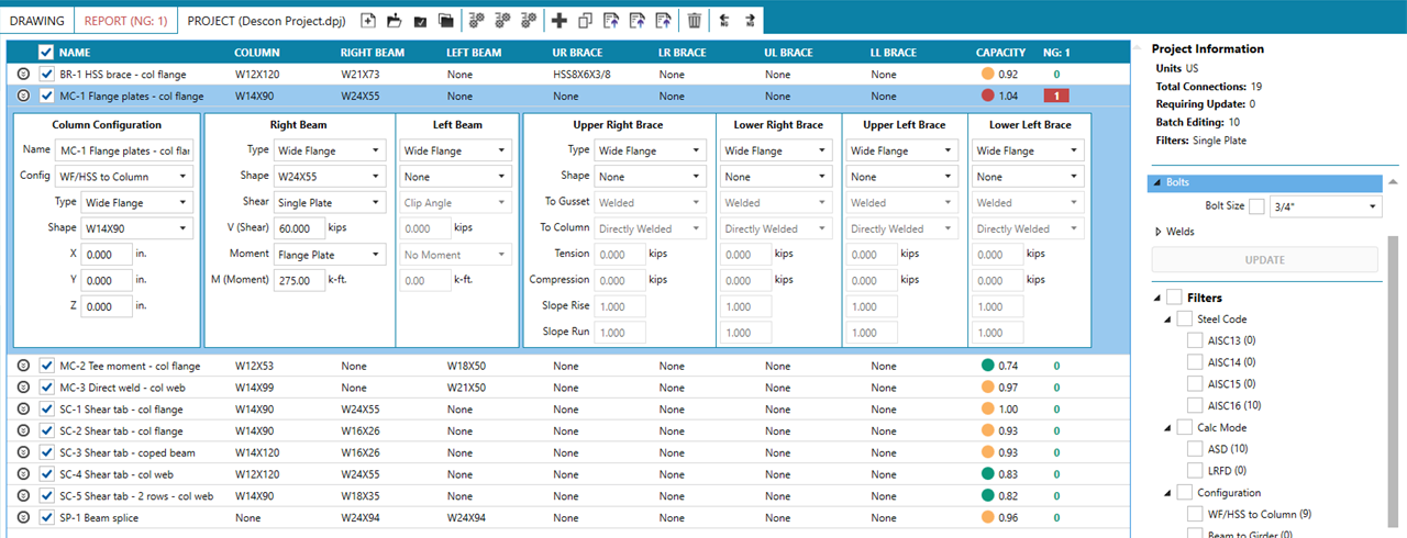
Only the values you tick are changed. A combination that does not apply to a connection is skipped, and Descon tells you when that happens. The bolt size goes to every bolt group in the connection. On a moment connection with bolted flange plates, that includes the flange plate bolts, which is how the next section comes about.
Finding what does not work
The NG heading is the first place to look after any change. After the bolt change above, it read 1. Press Go to Next NG in the project toolbar and Descon selects the next connection with a failing check and loads it in the design panel. Go to Previous NG goes the other way.
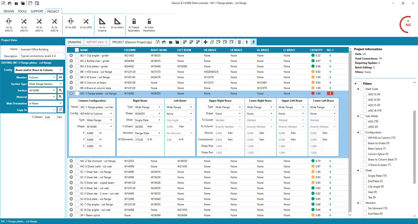
Switch to REPORT and press Go To Next NG in the report toolbar to jump to the line that fails.
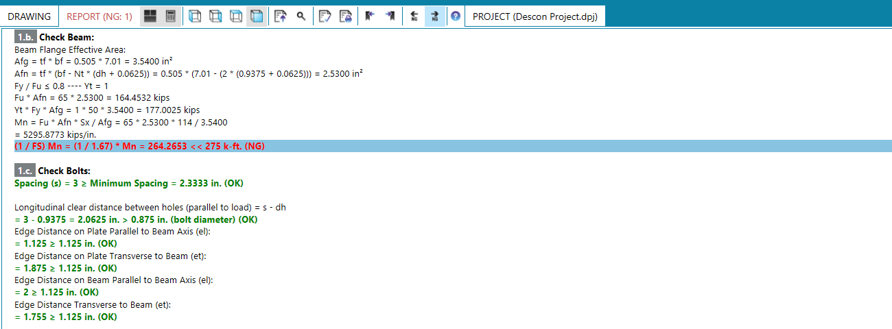
This one is a real consequence of the change. A 7/8 in. bolt needs a 15/16 in. hole, which takes more out of the W24X55's flange than a 3/4 in. bolt did. At the bolt holes, the flange's effective area drops to 2.53 in.², and the beam's allowable flexural strength there falls to 264.3 kip-ft, below the 275 kip-ft the connection carries. The fix is an engineering decision made on that one connection: keep 3/4 in. bolts in its flange plates, or change the beam. The other nine keep the new bolts.
Reports for the whole project
Tick the connections you want, or use the top box to tick them all, and press Calculate and Export Reports. Choose a folder and a format:
- PDF (No Drawings): one calculation report per connection.
- PDF (Include Drawings): the same, with the drawings. Slower, because each drawing is made in turn.
- Text or Rich Text: one file per connection, without the report's page formatting.
- CSV: a connection schedule, one file for each shear connection type.
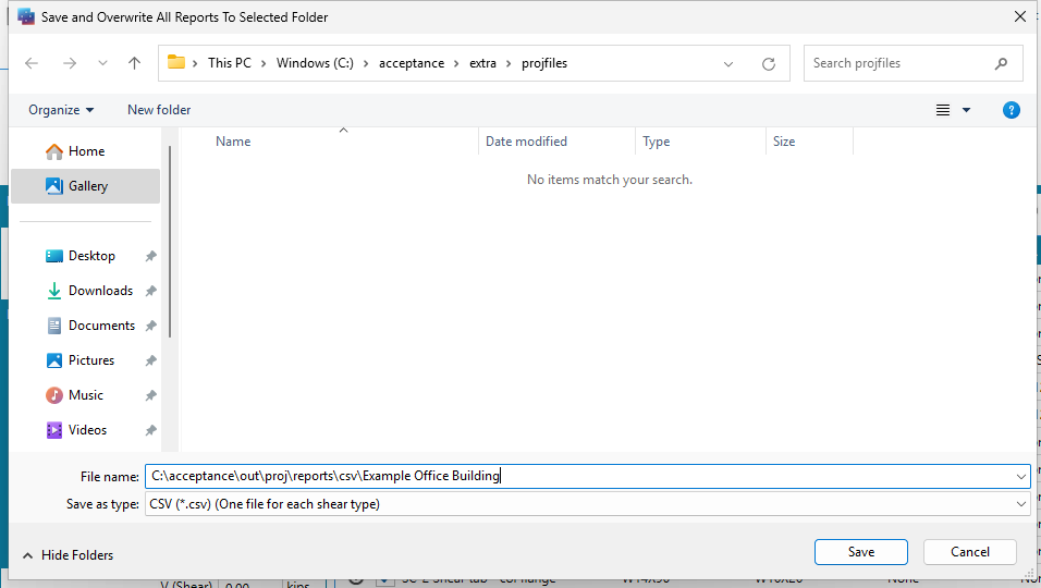
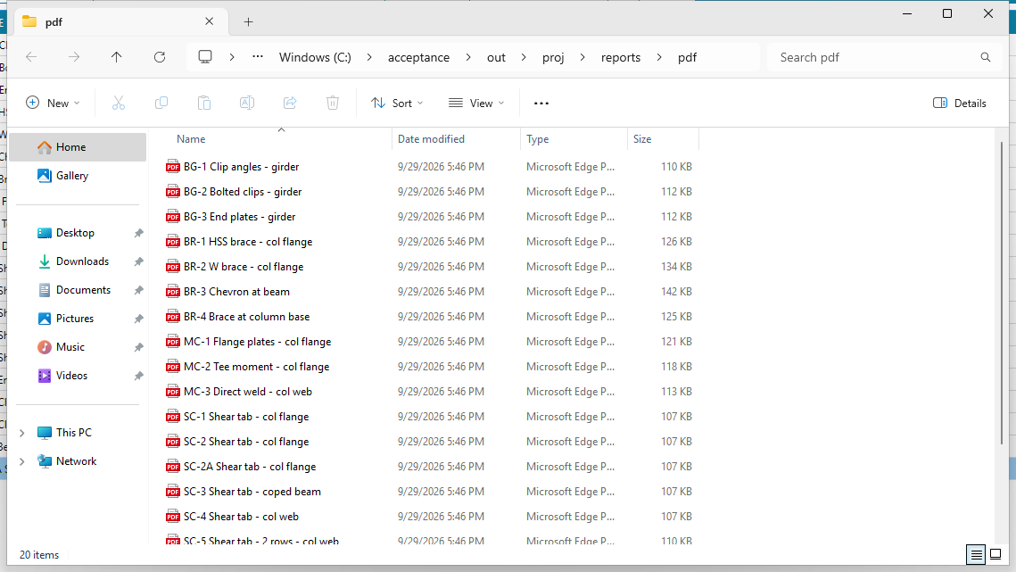
Each report is named after its connection, so a folder of them reads like the connection list. The twenty reports here took under ten seconds. Existing files of the same name are replaced.
The CSV schedule lists each single plate and clip angle connection with the dimensions a detailer needs: beam depth, bolt rows, plate or angle size, bolts, spacing and edge distances. This is part of the single-plate schedule from the example project:
| Mark | Framing type | D | #R | #C | W | B | Vertical bolt spacing |
|---|---|---|---|---|---|---|---|
| SC-1 Shear tab - col flange | BeamToWFlangeColumnFlange | 23.6 | 4 | 1 | 0.375 | 0.875A325N-STD | 3 |
| SC-2 Shear tab - col flange | BeamToWFlangeColumnFlange | 15.7 | 3 | 1 | 0.25 | 0.875A325N-STD | 3 |
| SC-3 Shear tab - coped beam | BeamToWFlangeColumnFlange | 15.7 | 3 | 1 | 0.375 | 0.875A325N-STD | 3 |
| SC-4 Shear tab - col web | BeamToWFlangeColumnWeb | 23.6 | 4 | 1 | 0.3125 | 0.875A325N-STD | 3 |
| SC-5 Shear tab - 2 rows - col web | BeamToWFlangeColumnWeb | 17.7 | 4 | 2 | 0.375 | 0.875A325N-STD | 3 |
| SC-2A Shear tab - col flange | BeamToWFlangeColumnFlange | 15.7 | 3 | 1 | 0.25 | 0.875A325N-STD | 3 |
D is the beam depth, #R and #C the rows and columns of bolts, W the weld, and B the bolt. Dimensions are in inches. The full file has a column for each dimension on the connection, as well as copes, edge distances and capacity.
Saving and sharing a project
Press Calculate and Save Project or Calculate and Save Project As... in the project toolbar. The whole project is one .dpj file, with every connection inside it. The nineteen-connection example is about 300 KB, small enough to email. To reopen it, press Open Project, or double-click the file. Descon calculates every connection as it opens.
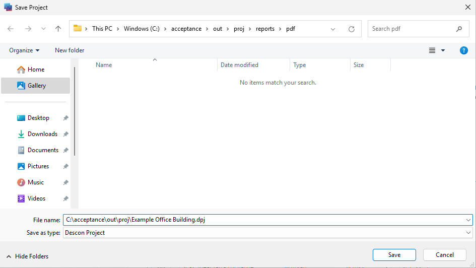
Save the project before you close Descon or open another design. Descon's own prompt when you close, and File → Save, save the connection you are editing as a .dsn file, not the project. That is also how you take one connection out of a project to send on its own: select its row, then use File → Save As.
The project toolbar
The toolbar appears beside PROJECT in the view bar. Its buttons show their names when you hover over them.
| Button | What it does |
|---|---|
| New Project | Starts an empty project with one blank connection. Save the current project first; you are not asked. |
| Open Project | Opens a .dpj file and calculates every connection in it. |
| Calculate and Save Project | Calculates what needs it and saves the project. |
| Calculate and Save Project As... | The same, under a new name. |
| Calculate | Calculates every connection marked UPDATE. |
| Calculate and Display | Calculates, then switches to the drawing. |
| Calculate and Export Reports | Calculates the ticked connections and writes a report for each, or a CSV schedule. |
| Add New Connection | Adds a blank connection to the end of the list. |
| Copy Selected Connections | Copies every ticked connection. |
| Import Connections From .dsn Files | Adds one connection for each design file you pick. |
| Remove Selected Connections | Removes the ticked connections, after asking. |
| Go to Previous NG / Go to Next NG | Moves to the previous or next connection with a failing check. |
Common questions
Does a project change my original .dsn files?
No. Importing copies each design into the project. Nothing you do in the project is written back to the files.
How many connections can a project hold?
There is no set limit. Descon calculates twenty connections at a time, and with more than two hundred to calculate it shows a progress window you can cancel.
Can different connections use different codes?
Yes. Each connection keeps its own steel code and design method, which is what the Steel Code and Calc Mode filters are for. The All to buttons bring them into line when you want that. Units are the exception: a project is either all imperial or all metric.
Why does a connection read 0.00?
It has not been calculated, usually because it was just added or copied. A copy or a new connection is calculated once something in it changes: edit it, then press Calculate.
Why is the Project tab missing?
Projects need the Next plan. The free trial includes it. Pricing has the plans, and an administrator can change yours from the portal.
Who can I ask if this page does not cover it?
Use Send Feedback in Descon, or email support@desconplus.com. We are the same people who wrote the software.